Controlling a four-axis robot arm

Gentle Touch
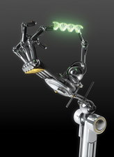
© Lead Image © marc heriche, Fotolia.com

© Lead Image © marc heriche, Fotolia.com

Article from Issue 226/2019
Author(s):

Learn the basics of robotics with a Raspberry Pi and a PiXtend controller.

Robotics might seem like a daunting subject to tackle, but a Raspberry Pi, a PiXtend module, Codesys control software, and a bit of Structured Text (ST) programming are all you need to get started in this compelling discipline. In this article, I describe how to set up and program a robot arm.

For this project, I opted for the four-axis robot arm by SainSmart [1]; it has a good price-to-performance ratio and a large working range. Simple hobby servos let the robot arm equipped with a simple gripper [2] move objects. The Thingiverse website provides the 3D printer files for printing the gripper [3]; alternatively, you can purchase the gripper on Amazon [4]. The gripper also is driven by a servo and requires a PWM signal for control. For more information on servos, see the box "How Servos Work."

How Servos Work

The servos used in this project are small motors you can get from hobby shops – not industrial servomotors like those found in the big robots of the automotive industry. Strictly speaking, hobby servos are not motors at all, but actuators. Although they have a motor, additional electronic components make them servos.

The servos used in this project are controlled by a pulse-width modulation (PWM) signal. Imagine a square wave signal with a constant frequency. Now change the ratio between pulse (on) and pause (off) – PWM really is that simple (Figure 1).

Figure 1: PWM control signal: A short pulse equals a small servomotor step; a long pulse equals a giant step.

PWM can be used to encode information in the pulse length. For the servomotors in this project, the length of the signal indicates which angular position the servo arm should assume. To make this work, a position sensor in the servo indicates where the servo arm is at the moment. An electronic controller continuously compares the actual position with the set point position and controls the motor so that the difference between the two is as small as possible. In practice, it is not always possible to achieve a difference of zero. When that happens, the servo starts humming. Inside the servo, a gear translates the rotary motion of the motor.

The most important characteristics of servos include the maximum angle difference of the servo arm, the force it applies, and its positioning speed. A servo with real ball bearings and metal gears lasts longer than a plastic servo with plain bearings. The differences in quality are also reflected in the price.

Now that you know how a servo works, you need to take a closer look at the PWM signal, which has a constant frequency of 50Hz, corresponding to a signal length of 20ms. Many servos can also be controlled with a shorter signal length (e.g., 10ms). The pulse length, on which the angular position of the servo depends, is 1-2ms.

The best way to keep track of the motors is to label each one (Table 1). Figure 2 shows the robot with the gripper, and the wiring diagram in Figure 3 shows how to connect the individual motors. Please note that hobby servos can handle a maximum of 6V.

Table 1

Motor Labels

Label

PiXtend Connection

Function

M1

PWM2A

Open and close gripper

M2

PWM1B

Rotate gripper

M3

PWM0B

Extend and retract arm

M4

PWM0A

Raise and lower arm

M5

PWM1A

Rotate arm in base

Figure 2: The complete, ready-to-use robot arm. The gripper was created on a 3D printer.
Figure 3: The wiring diagram shows how the servomotors on the robot arm and gripper are wired to the PiXtend.

Control

As mentioned, the PiXtend controls the motors. If you are not familiar with this controller yet, have a look at the "PiXtend at a Glance" box; the "PiXtend Technical Data" box summarizes the technical specs.

PiXtend Technical Data

  • 16 digital inputs (3.3V/5V/12V/24V)
  • 12 digital outputs (max. 30V; 0.5A each)
  • 6 PWM/servo outputs (6x16 bits)
  • 4 relays (max. 230V, 6A)
  • 4 voltage inputs (0-5V/0-10V)
  • 2 current inputs (0-20mA)
  • 2 analog voltage outputs (0-10V)
  • 4 GPIOs (5V)
  • Serial interface: RS232, RS485 (CAN)
  • Real-time clock (RTC) with battery buffering
  • Up to 4 DHT11/DHT22/AM2302 sensors (temperature and humidity)
  • Onboard voltage regulator
  • Input 12-24VDC (max. 30V)
  • Output 5VDC/2.4A (powers PiXtend V2 -L-, Raspberry Pi, and connected USB devices)
  • Retain/persistent memory: 64 bytes of flash EEPROM
  • Compatible with Raspberry Pi models B+/2B/3B/3B+
  • Certification: CE, RoHS

PiXtend at a Glance

The PiXtend V2 -L- is a professional expansion board for the Raspberry Pi. It features industry-compatible I/O ports and additional interfaces that the Raspberry Pi lacks. In addition to analog inputs and outputs, the board also includes relay outputs with a very high switching capacity.

A whole range of alternatives are available for programming. The Linux tools include some command-line programs that call the PiXtend functions, which means you can easily create scripts that handle the control tasks. FHEM is a widespread, Linux-based program for home automation that runs as a Perl server. The PiXtend Python Library provides an API that allows easy access to the PiXtend interfaces. OpenPLC is open source PLC software often used at universities. Thanks to the Node-RED IoT development tool, complex processes can be displayed graphically in a web front end. The Codesys IDE helps in creating programs for industrial controllers that many controller manufacturers use. If you learn how to use this programming environment, you can create programs for almost any controller on the market.

The PiXtend board used here is only one of many PiXtend variants. The manufacturer's website has detailed information about the different boards [5]. Although the PiXtend V1 is well suited for training and further education, the V2 variants are aimed more at professional use.

I am using the PiXtend V2 -L- [6], which has a large number of interfaces that let you implement almost any geek project. Before you start programming the robot, you need to install the Codesys software on the PiXtend and on a Windows PC. Thus far, no Linux version of the program is available.

The complete software – programs and packages for Codesys, including the sample application – can be found on the PiXtend website [7]. Version 3 of the Codesys Development System is freely available online [8]; the installation is driven by a wizard. For the development environment to work with the PiXtend, you need to install two additional packages [9] [10]. Just click on the downloaded files and the Codesys Package Manager will install them.

For the PiXtend itself, you also need the appropriate software, which is available as a preconfigured SD card image [11]. You will find a detailed description for setting up the complete software in the PiXtend [12] manual.

First Test

The basis for the test is a demo project [13] that lets you control the PWM outputs of the PiXtend individually. A graphical user interface allows access from the Raspberry Pi IP address. Alternatively, you can operate the front end from the Codesys IDE (Figure 4), which provides test options for all functions of the PiXtend.

Figure 4: The Codesys demo project opens up many options for accessing the PiXtend controller.

To put the robot into operation, you first need to choose the PWM tab for controlling the outputs (Figure 5), which should be set to Servo Mode. For commissioning, enable the individual PWM outputs one after the other and use the slider to set a position for the servo. The controller values allow a setting between 0 and 16,000. In the worst case, the servo will perform fast, uncontrolled movements; thus, you should center the PWM signal controls before activation.

Figure 5: The Codesys demo project lets you try out the various servomotor angular positions to find the optimal settings.

Now you have to find out which values correspond to the maximum and center positions of the servo – these values vary from model to model. Make a note of the final and median values. You can also mark the working range in the robot's workspace: This makes programming easier later. With the help of the demo project, values can be determined for all positions that the robot needs to occupy.

During the first tests, another problem occurs with very unpleasant side effects: If for any reason (blockage or overload) one of the servos draws so much current from the power supply that it breaks down, the control electronics of the remaining motors also will no longer work correctly. All the servos suddenly move uncontrollably and chaotically back and forth. To stop them, disable all PWM outputs; then, reactivate the servos individually to isolate the problem.

A laboratory power supply with built-in current monitoring is a massive help with troubleshooting. An indication that something is wrong is a deep hum generated by the servos when they can't reach a position. Even a continuous current of more than 600mA at a fixed servo position indicates a fault. However, sometimes higher currents also flow when moving. As soon as the motor has stopped, it should no longer consume electricity. After working through the tests described here, move on to the first genuine program.

Robot Arm in Action

To breathe life into the robot arm, you initiate a chain of steps to tell it when to move to a specific position. The sequence of steps realized in this project works on a purely time-controlled basis and, thus, is processed without external influences one position after another. The previous test already provided which values are required for specific positions of the robot arm.

The program uses the Pascal-style ST programming language, which is frequently used in industrial controllers. The control program uses a two-dimensional array to store the complete sequence: One dimension stores the number of the current step, and the second stores the five values of the individual servos, along with a value for the time in which the robot needs to reach the position.

Listing 1 shows the variables used by the program: The xInit variable initializes the controller in the PiXtend and must not be deleted, the lock variable prevents the sequence from starting several times, timer implements the time delay, and step saves the current step in which the sequence is located.

Listing 1

Variable Definitions


The control array is defined as a constant, because the values do not change at run time. If you want to make changes to one of the constants, you have to make sure to load the program on the PiXtend with the Login with download option (Figure 6); otherwise, the software will not update these constants.

Figure 6: If you change constants, you need to load the program by choosing the Login with download option; otherwise, the software will not adopt the changes.

The program (Listing 2) starts after the comment in line 7:

// put your program code here...

Listing 2

Positioning Sequence


The code that precedes that line needs the program to establish a communication channel between the PiXtend and the Raspberry Pi. The first step is to query the DI0 start button input (line 9) by using the alias for the complete input byte. The number after the period indicates which bit you want to query. If the button is pressed and the lock variable is set to FALSE (inactive sequence), the variable switches to TRUE, and the sequence starts to run.

In the next IF block starting in line 13, the code queries the lock variable. If it is set to TRUE, the block is processed – activating the PWM outputs of the PiXtend first. The sequence then loads the values for the current step into the control registers of the PWM outputs. The robot now moves to that position.

At the same time the registers are loaded, timer is loaded with the wait time from the array and started. After timer has expired, the step variable is incremented by 1 and timer is deactivated; then, everything starts all over again for the next step in the sequence. After all the steps have been executed, lock changes back to FALSE and step assumes a value of 1. The sequence is then ready for the next round.

The last IF block starting in line 38 switches the PWM outputs to FALSE at the end of the sequence, deactivating the servos completely, which means they should use hardly any power.

In a YouTube video [14] of the robot arm in action, you can see noticeably jerky motion sequences, because the servos always try to reach the new position at maximum speed. One way to reduce this jerk is to keep the changes in values in the PWM registers to a minimum. You can see this in the video to some extent when the arm transports the plush toy across the table in a few small steps so that the arm does not fling the toy out of the gripper.

To control the servos more sensitively, you would have to design the program to approach target positions in small steps. This programming is a bit more complex and is beyond the scope of this article, but it would be a good exercise for a rainy Sunday afternoon.

Buy this article as PDF

Express-Checkout as PDF
Price $2.95
(incl. VAT)

Buy Linux Magazine

SINGLE ISSUES
 
SUBSCRIPTIONS
 
TABLET & SMARTPHONE APPS
Get it on Google Play

US / Canada

Get it on Google Play

UK / Australia

Related content

  • PiXtend V2

    The PiXtend board extends the Raspberry Pi with many useful interfaces and functions for new target groups.

  • Halloween Vending Machine

    A Halloween vending machine frightens visitors, but the braver ones receive a chocolate reward.

  • GoPiGo3

    The GoPiGo3 kit provides components and software for a small robot car with a Raspberry Pi brain.

  • RaspPi-Controlled Toy Sailboat

    With Node-RED, you can create a web dashboard that instructs a Raspberry Pi to set the rudder position on a toy sailboat.

comments powered by Disqus
Subscribe to our Linux Newsletters
Find Linux and Open Source Jobs
Subscribe to our ADMIN Newsletters

Support Our Work

Linux Magazine content is made possible with support from readers like you. Please consider contributing when you’ve found an article to be beneficial.

Learn More

News