
Wireless thermo-hygrometer
Comfy Digs

© Lead Image © shamain, 123RF.com
A WiFi sensor monitors indoor humidity and temperature and a Node-RED dashboard reports the results, helping you to maintain a pleasant environment.
MQTT
The acronym MQTT stands for Message Queuing Telemetry Transport. The protocol was developed in 1999 to monitor oil pipelines, but it is still in use today for distributed measurement in the professional sector. Today, the MQTT protocol is increasingly used in the IoT environment, because its low network load and low CPU consumption make it particularly suitable for such applications.
MQTT has three components: a message generator (publisher), a message recipient (subscriber), and a broker that decouples the communication between publisher and subscriber. Therefore, not all components have to be online at the same time to transmit messages.
To ensure that messages are not transmitted in a disorderly manner, MQTT has a tree structure of topics (i.e., message channels that bundle certain types of transmissions). For example, a topic could comprise Building/Floor/Room/Sensor/Temperature. If you want to retain the values of all temperature sensors in a building, you can use wildcards within topics (e.g., Building/+/+/Sensor/Temperature).
MQTT libraries exist for many programming languages. By default, the service runs on TCP port 1883. Further information about the MQTT protocol can be found on the official project website [1].
If you live in a dry climate – or a hot region that requires air conditioning – you might find that your skin starts to feel taut: a good indication that the room air is too dry. Typical thermo-hygrometers can help you monitor humidity and room temperature, but they are usually stationary devices that can only be read when standing right in front of them.
In this article, I build a thermo-hygrometer to keep track of the temperature and humidity in your home. The device connects to a WiFi network and relies on an MQTT server to display its measured values on a Node-RED dashboard. For more information on the MQTT messaging protocol, refer to the "MQTT" box.
Initially, building your own wireless thermo-hygrometer doesn't sound that complicated, but after taking a closer look, you will realize that getting to the finished project involves a large number of individual steps.
MQTT
Like Node-RED, the MQTT server runs on the Raspberry Pi. Information about setting up Node-RED can be found in a previous article [2]. I use Mosquitto as the MQTT server; you can install it, query its status, start it, and stop it with the following:
$ sudo apt update
$ sudo apt upgrade
$ sudo apt install mosquitto mosquitto clients
$ sudo service mosquitto status
$ sudo service mosquitto start
$ sudo service mosquitto stop
To test the server for functionality, open three terminal connections to the Raspberry Pi. In two of them, launch a Mosquitto subscriber for the raspberry topic:
$ mosquitto_sub -h localhost -v -t raspberry
In the third terminal, start a publisher that sends a message for the raspberry topic:
$ mosquitto_pub -h localhost -t raspberry -m "Raspi talks MQTT!"
After sending the message, it appears on the two subscriber terminals. Alternatively, messages can also be sent or received with the MQTTBox Chrome app [3] (Figure 1).
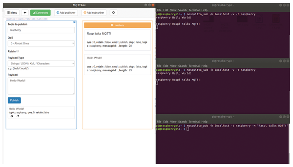 Figure 1: A typical example of an MQTT message transfer with multiple clients.
The Sensor
Figure 2 shows the complete circuit diagram of the sensor. You can solder the components onto a prototype board or plug them into a PCB Prototyping Board [4]. An ESP8266 microcontroller with built-in WiFi is the central component. The calibrated digital AM2321 sensor measures temperature and humidity and is read from the I2C interface. Connect the sensor to the ESP8266 on GPIO4 and GPIO5.
 Figure 2: The circuit diagram for the thermal-hygrometer sensor. The heart of the circuit is the AM2321 temperature and humidity sensor and ESP8266 microcontroller.
A USB-to-serial module, which you plug in to the test board from a pin header, is used to program the ESP8266. This setup makes it easy to remove the module to program other sensors. Two 1.5V batteries serve as the power supply; the C1 capacitor in the circuit keeps the operating voltage of the ESP8266 stable.
The LED on GPIO14 is for test purposes. Special attention should be paid to the GPIO16 connection: The internal timer that wakes the ESP8266 from its deep sleep phase so it can transmit the currently measured value depends on this. The R7 and R8 resistors serve as pull-up resistors for the I2C bus. They ensure that the signal levels on the SDA and SCL lines are clean. All other components – four 10K resistors and two jumpers – are needed to program and operate the ESP8266.
As Figure 3 shows, the ESP8266 is soldered to an adapter board that is connected to the base board by a pin header. Some of these adapter boards already come with some of the resistors necessary for operation. Examples of the components needed for the project include:
- ESP8266 and ESP adapter [5]
- USB-to-serial adapter [6] (if not included in your ESP8266 kit)
- AM2321 [7]
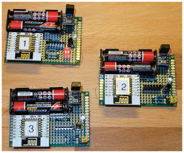 Figure 3: The three completely assembled MQTT sensors transmit the humidity and temperature to the MQTT server wirelessly at one-minute intervals.
Arduino IDE
To write programs for the ESP8266 you need an appropriate development environment. The Arduino IDE, which you can download from the project's homepage [8], is ideal: Just select the appropriate version for your operating system and install it. To start the development environment, change to the installation directory and enter ./arduino on the command line.
Now, you have to adjust the IDE for the ESP8266 by entering the URL http://arduino.esp8266.com/stable/package_esp8266com_index.json in the Additional Boards Manager URLs text box under File | Preferences. The development environment then adds the parameters required for the ESP8266 to the list of board managers.
To install the board manager for the microcontroller, go to Tools | Board: <Board> | Boards Manager, find and select the ESP8266 entry, and click Install. Next, click Tools | Board: <Board> | Generic ESP8266 Module. To upload programs to the ESP8266, you need to connect the USB-to-serial adapter to your computer. Figure 4 shows all the settings needed to upload a program without errors.
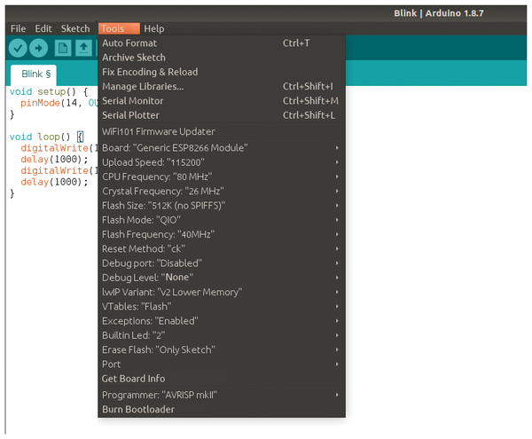 Figure 4: If you use the communication settings shown here in the Arduino IDE, uploading programs to the microcontroller should work smoothly.
Buy this article as PDF
(incl. VAT)
Buy Linux Magazine
US / Canada
UK / Australia
Subscribe to our Linux Newsletters
Find Linux and Open Source Jobs
Subscribe to our ADMIN Newsletters
Support Our Work
Linux Magazine content is made possible with support from readers like you. Please consider contributing when you’ve found an article to be beneficial.

News
-
So Long Neofetch and Thanks for the Info
Today is a day that every Linux user who enjoys bragging about their system(s) will mourn, as Neofetch has come to an end.
-
Ubuntu 24.04 Comes with a “Flaw"
If you're thinking you might want to upgrade from your current Ubuntu release to the latest, there's something you might want to consider before doing so.
-
Canonical Releases Ubuntu 24.04
After a brief pause because of the XZ vulnerability, Ubuntu 24.04 is now available for install.
-
Linux Servers Targeted by Akira Ransomware
A group of bad actors who have already extorted $42 million have their sights set on the Linux platform.
-
TUXEDO Computers Unveils Linux Laptop Featuring AMD Ryzen CPU
This latest release is the first laptop to include the new CPU from Ryzen and Linux preinstalled.
-
XZ Gets the All-Clear
The back door xz vulnerability has been officially reverted for Fedora 40 and versions 38 and 39 were never affected.
-
Canonical Collaborates with Qualcomm on New Venture
This new joint effort is geared toward bringing Ubuntu and Ubuntu Core to Qualcomm-powered devices.
-
Kodi 21.0 Open-Source Entertainment Hub Released
After a year of development, the award-winning Kodi cross-platform, media center software is now available with many new additions and improvements.
-
Linux Usage Increases in Two Key Areas
If market share is your thing, you'll be happy to know that Linux is on the rise in two areas that, if they keep climbing, could have serious meaning for Linux's future.
-
Vulnerability Discovered in xz Libraries
An urgent alert for Fedora 40 has been posted and users should pay attention.