An introduction to electronic weighing

Weighing In
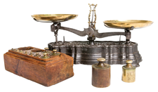
© Lead Image © Carlos Velayos, 123RF.com

© Lead Image © Carlos Velayos, 123RF.com

Article from Issue 249/2021
Author(s):

Create your own weighing device with easily available components and open source software.

In this article, I discuss the design of a compact and portable workshop balance for various single-load-cell weighing applications constructed with a small load cell, an instrumentation amplifier, an excitation supply, a microcontroller, a display, and a serial port for debugging. Throughout, I used Linux and open source software, and I provide code samples, with directions for finding the complete code online.

History

Ancient civilizations used simple balances to compare weights for trading in precious metals, spices, salt, and the like. Today's civilization is no less dependent on knowing the weight of objects. It is hard to imagine a day in which the knowledge of weight does not take part: from the morning visit to the bathroom scales, a trip to the supermarket, baking a cake, to weighing baggage at the airport – the list of times weight plays a part in our lives seems endless. Today, we've moved away from mechanical balances, for the most part, obviating the need for ready reference weights.

Today's weighing equipment is usually based on electronic signals from strain gauges. These sensors are thin-film resistors whose resistance varies in response to tension or compression. When bonded to a mechanical structure subject to the force of an applied mass, the resistance of a strain gauge will change proportionally in response. Practical weighing systems use more than one strain gauge, and these are generally bonded to a metallic billet in a controlled manner to form a more complex electrical circuit designed to eliminate nonlinearities and temperature effects. These billets are known as load cells and are available commercially with working ranges from a few grams to hundreds of tonnes.

Load cells (Figure 1) are built into the structures of complete weighing systems such as scales, weighbridges, hoists, and counting scales in such a way that they can be replaced easily should the need arise. Although load cells are transducers with no moving parts, of course they do deflect slightly under load, and that allows mechanical endstops to be used to limit the deflection and protect the cell from overload. It should be noted that larger weighing machines such as weighbridges will employ more than one load cell, a typical arrangement being a rectangular platform with a load cell at each corner. The signals from each load cell are summed electronically to provide a total weight. Often, a range of load cells of different capacities will share the same basic billet, machined in different ways.

Figure 1: A typical modern load cell. The strain gauges are covered with a white flexible coating to protect them.

Load Cell Operation

In most load cells, four strain gauges are employed – two in tension and two in compression – in a symmetrical manner to eliminate temperature effects (Figure 2). The strain gauges are arranged into a Wheatstone bridge (Figure 3).

Figure 2: The arrangement of the strain gauges on the load cell billet and the forces that act on them. The "dumbbell" shape cut out of the billet makes the metal thinner in the vicinity of the strain gauges, increasing sensitivity.
Figure 3: This electrical arrangement is attributed to Charles Wheatstone [1], a Victorian physicist. It is very useful in this type of measurement because it allows the user to "null out" the standing voltages in a system and thus make accurate measurements of small changes.

A strain gauge is a sensor whose resistance varies with applied force, so that if you can measure resistance, you can measure that force. The conducting material (often constantan) is deposited onto an insulating substrate such as polyimide. The conductor is designed in a serpentine shape (Figure 4) such that extension by applied force in the longitudinal direction is much higher than that in the lateral direction. This arrangement reduces sensitivity to off-axis load. Pads are provided at the ends of the conductor so that lead-out wires may be soldered or otherwise bonded to them.

Figure 4: Strain gauge conducting material design.

The Wheatstone bridge requires a voltage across it to provide an output, and that voltage is called the excitation voltage. The output of the bridge is a differential, which slightly complicates the electronics, as you will see later. At zero load, the difference between the two outputs should be zero, and as load is applied, one arm will go positive while the other goes negative. The differential output at full scale is measured in millivolts per volt (mV/V) (i.e., a ratio of output versus the excitation voltage). Excitation voltages are generally in the range of 5V to 20V, and a typical load cell might have an output of 2mV/V, making 20mV output at full scale for 10V excitation. From this, it can be seen that you are dealing with very small voltages, especially when you require high precision. The upside of this arrangement is that much the same electronics can be applied to a wide variety of different weighing applications, because the load cell's maximum output will be similar in all cases.

The nominal resistance of the strain gauges is on the order of a few hundred ohms, so a bridge made up of four 400-ohm gauges will have a resistance (R) of 400 ohms, as seen by the excitation supply; thus, it can be see that some power is required to excite the load cell, which can be a challenge for battery-operated systems. In this case, lowering the excitation voltage saves power at the expense of full-scale output and, ultimately, precision. Although increasing the excitation voltage might seem attractive from the point of view of increasing load cell output, there comes a point when the strain gauges will self-heat, causing local expansion of the load cell billet and the attendant inaccuracy.

In a little more detail, the output of the load cell can be calculated in the following manner: V-=R2/(R1+R2) x Vex, whereas V+=R3/(R3+R4) x Vex, so the differential output voltage is:

Tare and Span: Calibration

One factor that must be considered when choosing a load cell for an application is tare, which refers to the weight of any structure supported by the load cell before any object to be weighed is placed on it. This tare might be the mixing bowl on a kitchen scale before ingredients are added or the platform required to support a multitonne truck on a weighbridge. Tare can represent a large portion of the ultimate full-scale range of a system and must be taken into account at the design stage.

Further removal of tare is sometimes required during normal operation: Again, using the example of a weighbridge on which a truck is to be loaded with goods, the initial zero point would be with the weighbridge empty. Once an empty truck is driven onto the weighbridge, it is convenient to again "zero" the weight display so that as goods are added to the truck, the display reflects what has been added, without the complication of the truck's tare. In the case of a weighing system designed to dispense ingredients in a fixed ratio (batch weighing) into a vessel (e.g., flour, water, yeast, and sugar in a bakery), the tare may be reset several times as the batch is assembled with the different ingredients.

"Span" is the term used to describe the full range of a weighing machine. The desired span is application dependent, and the load cell(s) must be chosen to have sufficient capacity for the required span plus tare, as described above. The stated output of the load cell at full scale is generally a nominal figure only, meaning the instrument must be calibrated before use at intervals during its operational life because of various mechanical and temperature effects. For a small instrument, this is a simple undertaking, reference weights being readily available at varying levels of precision from commercial sources [2], some of which can be traced back to national and international standards bodies.

For larger systems, calibration can be a complex and expensive exercise because you have no way to avoid the use of dead weights for calibration, and moving such weights around is time consuming and expensive.

Buy this article as PDF

Express-Checkout as PDF
Price $2.95
(incl. VAT)

Buy Linux Magazine

SINGLE ISSUES
 
SUBSCRIPTIONS
 
TABLET & SMARTPHONE APPS
Get it on Google Play

US / Canada

Get it on Google Play

UK / Australia

Related content

  • Programming the Cell

    The Cell architecPIture is finding its way into a vast range of computer systems – from huge supercomputers to inauspicious Playstation game consoles. We'll show you around the Cell and take a look at a sample Cell application.

  • Neural Networks

    3, 4, 8, 11… ? A neural network can complete this series without knowledge of the underlying algorithm – by a kind of virtual gut feeling. We’ll show you how neural networks solve problems by simulating the behavior of a human brain.

  • Solar-Powered Mini PC with Puppy Linux

    The Aleutia E1 is a Mini PC with Puppy Linux on board designed for deployment in areas far away from power sources.

  • WiFi Thermo-Hygrometer

    A WiFi sensor monitors indoor humidity and temperature and a Node-RED dashboard reports the results, helping you to maintain a pleasant environment.

  • Latitude 2100: Netbook Not Just for Students

    Dell takes the new 10" 2100 netbook out of its Latitude business series to target students, but it also serves as a mobile business device. Ubuntu 8.10 runs on it.

comments powered by Disqus
Subscribe to our Linux Newsletters
Find Linux and Open Source Jobs
Subscribe to our ADMIN Newsletters

Support Our Work

Linux Magazine content is made possible with support from readers like you. Please consider contributing when you’ve found an article to be beneficial.

Learn More

News